
- New CQ2 body for the existing C(L)KQG Pin Clamp Cylinder, Built-in standard magnet (Bore Size of 50 mm).
- D-P3DWA type compact magnetic field resistant auto switch mountable, shortening protrusion by 5 mm compared with the D-P4DW type auto-switch.
- Possibility to mount 2 auto switches on the same surface.
- Wide range of guide pin types.
- Optional locking mechanism available.
- Precision adjustment of clamping height by choosing the with-shim type (0.5-3 mm).
- 4 selectable body types.

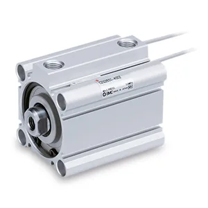
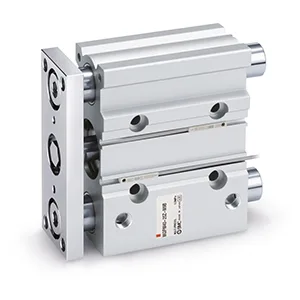
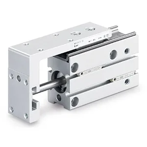
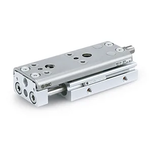
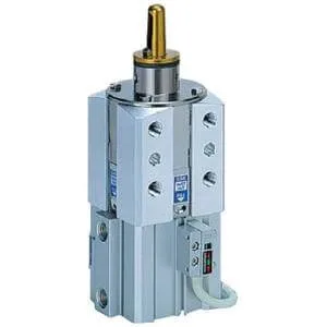 Series image. Appearance may vary by model and options.
Pneumatic actuators
C(L)KQG*50
C(L)KQG*50, Pin Clamp Cylinder, Built-in Standard Magnet
Explore the features, model options and technical documentation for C(L)KQG*50. Contact Pnoneks to select the full part number for your application.
SMC ·Clamp Cylinders
Request a quote for your application.
Share your part number and quantity so we can confirm pricing and lead time.
Selecting C(L)KQG*50
Selecting C(L)KQG*50: review the full part number and your system conditions when considering this Pneumatic actuators record. Share Lock, Body Shape, Mounting Surface, Bore Size, Port Thread, Guide Pin Diameter, Guide Pin Shape, Clamp Arm Position, Clamping Height, Shim, Auto Switch, Lead Wire or Pre-wired Connector, Number, the required quantity and your application notes with Pnoneks. Final compatibility and lead time are confirmed during quotation.
ABOUT THE PRODUCT
The essentials for selection.
- Manufacturer
- SMC
- Series
- C(L)KQG*50
- Product group
- Pneumatic actuators
- Function
- Clamp Cylinders
- Applications
- Suitability is evaluated against technical specifications and application conditions.
- Selection parameters
- Lock, Body Shape, Mounting Surface, Bore Size, Port Thread, Guide Pin Diameter, Guide Pin Shape, Clamp Arm Position, Clamping Height, Shim, Auto Switch, Lead Wire or Pre-wired Connector, Number
Exact dimensions, operating ranges and compatibility depend on the full part number. Review the relevant SMC documentation and application conditions for technical selection.
TECHNICAL PRODUCT INFORMATION
Features and model options
Technical descriptions and values below are preserved in the manufacturer’s original language. Options describe alternatives within the series; not every combination is valid. We will verify the full part number when quoting.
| Parameter | Options / values |
|---|---|
| Lock | None · L (With Lock) |
| Body Shape | D (Mounting Tap: 4xM10 x 1.5, Pin Hole: 2xØ8H7) · K (Mounting Tap: 2xM10 x 1.5, Pin Hole: 2xØ10H7) · M (Mounting Tap: 2xM12 x 1.75, Pin Hole: 2xØ10H7) · U (Mounting Tap: 2xM10 x 1.5, Pin Hole: 2xØ8H7) |
| Mounting Surface | A (90° from Port Location) · B (Same Side as Port Location) · C (Taps Diagonal Top Left, Right and Bottom Left, Right) · D (Taps Diagonal Top Left, Right and Bottom Left, Right) · E (Taps Diagonal Top Right, Left and Bottom Right, Left) · F (Taps Diagonal Top Right, Left and Bottom Right, Left) |
| Bore Size | 50 mm |
| Port Thread | Rc · TN (NPT) · TF (G) |
| Guide Pin Diameter | 125 (12.5mm) · 127 (12.7mm) · 128 (12.8mm) · 129 (12.9mm) · 130 (13.0mm) · 145 (14.5mm) · 147 (14.7mm) · 148 (14.8mm) · 149 (14.9mm) · 150 (15.0mm) · 155 (15.5mm) · 157 (15.7mm) · 158 (15.8mm) · 159 (15.9mm) · 160 (16.0mm) · 175 (17.5mm) · 177 (17.7mm) · 178 (17.8mm) · 179 (17.9mm) · 180 (18.0mm) · 195 (19.5mm) · 197 (19.7mm) · 198 (19.8mm) · 199 (19.9mm) · 200 (20.0mm) · 245 (24.5mm) · 247 (24.7mm) · 248 (24.8mm) · 249 (24.9mm) · 250 (25.0mm) · 295 (29.5mm) · 297 (29.7mm) · 298 (29.8mm) · 299 (29.9mm) · 300 (30.0mm) |
| Guide Pin Shape | D (Diamond Type) · R (Round Type) |
| Clamp Arm Position | A (Same Direction as Port) · B (90° From Port) · C (180° From Port) · D (270° From Port) |
| Clamping Height | L (Low Type) · H (High Type) |
| Shim | None · S (With 3 mm shims) |
| Auto Switch | No Switch · P4DW--Solid State Switch, 2-colour Indication, Magnetic Field Resist., 2 Wire · P3DWA--Solid State Switch, 2-colour Indication, Magnetic Field Resist., 2 Wire |
| Lead Wire or Pre-wired Connector | 0.5 m (Or None in the Case of No Switch) · L (3 m) · Z (5 m) · SC (0.3 m Cord Length, M12-4 Pin Connector, 3 & 4 Out) · SE (0.3 m Cord Length, M12-4 Pin Connector, 1 & 4 Out) |
| Number | 2 pcs. (Or None in Case of No Switch) · S (1 pc.) |