
SMC Authorized Reseller
Monday–Friday · 09:00–18:000850 811 86 07
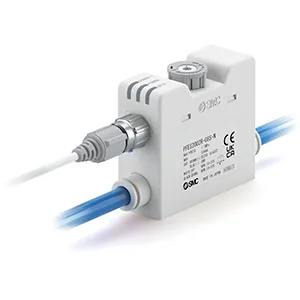
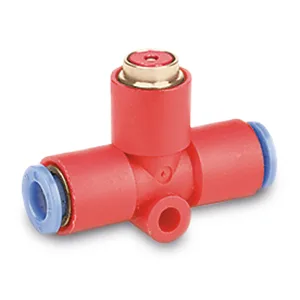
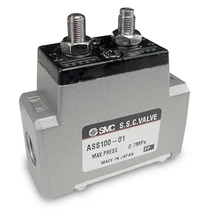
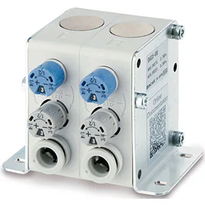
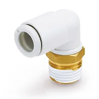
SMCDAS Deceleration Controller – DASSeries image. Appearance may vary by model and options.
Fittings & tubing

DAS

Deceleration Controller – DAS

Explore the features, model options and technical documentation for DAS. Contact Pnoneks to select the full part number for your application.

SMC ·Flow Control Valves and Equipment

Request a quote for your application.

Share your part number and quantity so we can confirm pricing and lead time.

Your message opens in WhatsApp. You can review and edit it before sending.

Selecting DAS

Selecting DAS: review the full part number and your system conditions when considering this Fittings & tubing record. Share Body Size, Mounting, Applicable Tubing O.D., the required quantity and your application notes with Pnoneks. Final compatibility and lead time are confirmed during quotation.

ABOUT THE PRODUCT

The essentials for selection.

Manufacturer
SMC
Series
DAS
Product group
Fittings & tubing
Function
Flow Control Valves and Equipment
Applications
Suitability is evaluated against technical specifications and application conditions.
Selection parameters
Body Size, Mounting, Applicable Tubing O.D.

Exact dimensions, operating ranges and compatibility depend on the full part number. Review the relevant SMC documentation and application conditions for technical selection.

TECHNICAL PRODUCT INFORMATION

Features and model options

Technical descriptions and values below are preserved in the manufacturer’s original language. Options describe alternatives within the series; not every combination is valid. We will verify the full part number when quoting.

Smooth motion

  • Reduce the impact of the stroke end – Dual-speed control of the cylinders
  • Save space – Up to 76 % reduction of the required space compared to a system of valves, fittings and speed controllers
  • Use it in your difficult-to-access applications – Easy installation between the valve and the cylinder
  • Adjust it easily – Flow rate controlled by two push-lock knobs with indicator.
More features

  • Applicable Tubing O.D.: Ø 4 to Ø 12 mm and Ø 5/32" to Ø 1/2"
  • Operating Pressure Range: 0.2 to 0.7 MPa.
Selection fields published in the source
ParameterOptions / values
Body Size5 · 7
MountingBoth Sides · L (Left Side) · R (Right Side)
Applicable Tubing O.D.04 (Ø4 mm) · 06 (Ø6 mm) · 08 (Ø8 mm) · 10 (Ø10 mm) · 12 (Ø12 mm) · 03 (ø5/32") · 07 (ø1/4") · 09 (ø5/16") · 11 (ø3/8") · 13 (ø1/2") · 03 (ø5/32\") · 07 (ø1/4\") · 09 (ø5/16\") · 11 (ø3/8\") · 13 (ø1/2\")
Let’s find your solution